Jeff Annis tells how to set up a wing stalling DT system
DT System for Small Embryo Model by Jeff Annis
This last spring I had considered building an Embryo semi scale model for small field flying on calm evenings or days. Decided on the Go Devil (Herb Kothe design) and obtained a short kit from Volare model products. In order to receive maximum bonus points the Embryo model must have a clear wind shield and wheel pads (covers over the wheels). Embryo models are limited to 50 square inches of wing area and including rubber are very light at 15 to 20 grams, thus making them susceptible to thermal fly-aways. Before getting to far into the build I had to determine which DT system to use. The criteria decided upon was a wing leading edge tilt DT, easily removable wing, secured wing hold down at leading and trailing edge (4 contact points), and DT fuse located on the side of the fuselage. After doing an extensive search on the internet and incorporating a few of my own ideas I finally came up with a design concept.
Following is a description of the DT system developed: The wing pivots about the trailing edge which is back stopped by a 1/16 square balsa strip glued to the fuselage. Two hooks are attached to either side of the fuselage and two more hooks are glued to ribs about 1 inch ahead of the trailing edge. A rubber band is then stretched from one side of the fuselage, around the two hooks on the wing, and back to the opposite side of the fuselage. Both fuselage hooks are positioned such that the wing trailing edge is pulled back and down against the stop. The wing leading edge is secured with two additional hooks glued to ribs on either side of the fuselage and on the wing leading edge. A line then runs from the opposite side of the fuselage, thru the two hooks on the wing leading edge and around a post on the bottom fuselage side. A DT band is attached to the end of this line and stretched to another hook on the fuselage side. This design rigidly secures the wing at two points on the leading and trailing edges. A wing DT limit line is looped over the wing and attached to the fuselage side at the edging edge and trailing edge locations.
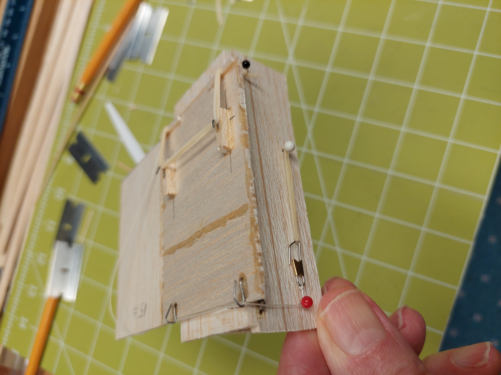
A proof-of-concept prototype was then made out of scrap balsa to evaluate this design. Everything worked fine except the trailing edge bands did not have enough torque to lift the wing into the DT position. This issue was resolved by adding a 1/16 square balsa strip at the wing trailing edge. By doing this, the band tension vector force angle was changed to increase the pulling torque applied to the pivoting wing. The following photos show the proof- of- concept proof type and the DT system in both flying and DT positions.
Proof-of-Concept Model
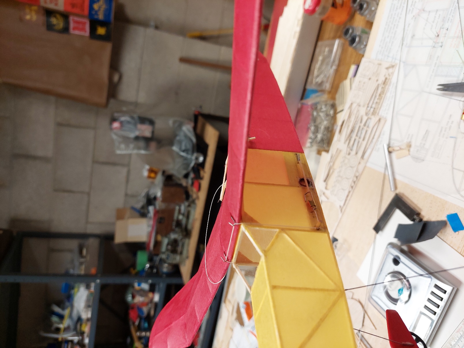
Wing in DT Position

Trailing edge Hold Down Bands

Wing in Flying Position and DT Band with Snuffer Tube